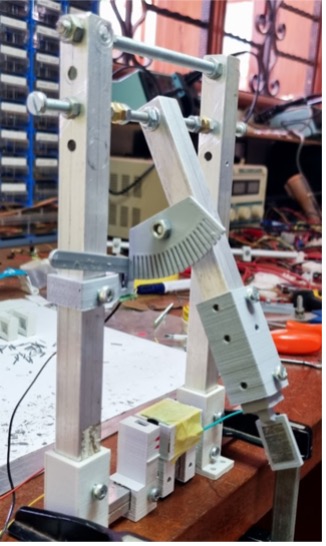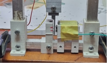
 De slinger opstelling.

The plate consists of stacked small transformer steel plates 11×1.5×0.5 mm and 18 mm high. This is to avoid Eddy currents!
On one side of the pendulum plate is the permanent magnet.
On the other side is a coil. This coil can be switched on or off.
With this set-up we can test with stronger coil magnet force (the induction generated magnet is weak).
So to find the force of the coil to work against the movement we can have a stronger coil magnet.
I measured with an opto-coupler when the pendulum was at the lowest point.
At that point the coil was switched off, to avoid the effect of the outgoing plate. At the highest point the coil was switch on again. So, only the effect of the ingoing plate was measured.
The total time was measured when the pendulum came to a standstill. Also was measured the time when the coil was never on. The difference between the 2 times will give us our answers!
Here are the results:
| test met de magneet en de spoel met ompoler in de N-Z stand (alle tijden in milliseconden) N-Z half aan & half N-Z off | ||||||||||||
| aan | aan | aan | aan | aan | uit | uit | uit | uit | uit | |||
| 332 | 333 | 319 | 318 | 317 | 323,8 | 317 | 316 | 317 | 316 | 328 | 318,8 | |
| 312 | 314 | 329 | 330 | 330 | 323 | 327 | 328 | 329 | 329 | 313 | 325,2 | |
| 325 | 325 | 314 | 313 | 314 | 318,2 | 314 | 313 | 313 | 313 | 321 | 314,8 | |
| 306 | 306 | 326 | 326 | 325 | 317,8 | 322 | 323 | 322 | 323 | 307 | 319,4 | |
| 312 | 314 | 307 | 304 | 306 | 308,6 | 306 | 305 | 308 | 304 | 310 | 306,6 | |
| 290 | 292 | 314 | 313 | 313 | 304,4 | 311 | 309 | 309 | 308 | 293 | 306 | |
| 272 | 277 | 294 | 290 | 289 | 284,4 | 293 | 289 | 293 | 292 | 279 | 289,2 | |
| 248 | 255 | 278 | 271 | 273 | 265 | 279 | 274 | 276 | 280 | 256 | 273 | |
| 246 | 247 | 257 | 243 | 243 | 247,2 | 255 | 244 | 254 | 251 | 248 | 250,4 | |
| 186 | 192 | 246 | 245 | 246 | 223 | 249 | 248 | 247 | 248 | 181 | 234,6 | |
| 244 | 245 | 194 | 182 | 180 | 209 | 184 | 175 | 178 | 177 | 251 | 193 | |
| 162 | 165 | 242 | 242 | 243 | 210,8 | 250 | 255 | 254 | 253 | 148 | 232 | |
| 243 | 244 | 164 | 158 | 157 | 193,2 | 151 | 146 | 147 | 147 | 295 | 177,2 | |
| 152 | 153 | 243 | 245 | 245 | 207,6 | 282 | 297 | 298 | 297 | 141 | 263 | |
| 246 | 247 | 150 | 147 | 147 | 187,4 | 141 | 142 | 140 | 140 | 334 | 179,4 | |
| 145 | 144 | 246 | 252 | 254 | 208,2 | 380 | 354 | 319 | 334 | 144 | 306,2 | |
| 258 | 258 | 144 | 140 | 142 | 188,4 | 142 | 142 | 144 | 143 | 161 | 146,4 | |
| 140 | 141 | 260 | 273 | 275 | 217,8 | 185 | 174 | 158 | 165 | 151 | 166,6 | |
| 274 | 273 | 139 | 140 | 140 | 193,2 | 148 | 150 | 151 | 150 | 149,75 | ||
| 142 | 142 | 271 | 263 | 260 | 215,6 | |||||||
| 255 | 255 | 144 | 146 | 147 | 189,4 | |||||||
| 5235 | 5267 | 5449 | 5141 | 5146 | 5247,6 | 4836 | 4952 | 4757 | 4770 | 4461 | 4755,2 | |
| With EM& Mag | No EM & Mag | |||||||||||
| – Hi&Low | 5216,0 | 4787,7 |
If the time of the pendulum is longer, then that means that there was less resistance. Or that there was a force helping the swing a bit.
The measurement was done 5 times, 1 with the coil (EM) on (aan) and 1 with the coil (EM) off (uit). That sequence 5 times, then we got the average over those measurements.From the results, it is very clear that when the coil (EM) is on, there is a force helping it to swing longer than when the coil (EM) was off! (In line with my assumption that magnets attract metals plates, never repel!)
This force must come from coil magnet in the ingoing faze, as it is the only change with no coil on!
Another proof that the ingoing plate is not working against the movement of the plate, it is actually helping that movement.
The movement of the plate is exactly as it would move (rotate) in a generator.
So, I come to the exciting and disturbing conclusion that the coil can generate electricity without putting the required energy in!?